
For my next project, and this is one I have been wanting to do for while, I will be making a speedometer for my remote control car.
"What good is that?" I hear you say, "how are you going to read the speed when it's going past you at 30 miles per hour!?"
Well I intend to log the speed to a SD card, so that it can be reviewed on a computer by the means of some pretty graphs and statistics. A display could be added to the car to show the maximum speed achieved or something, but I'm going to concentrate on logging to card to begin with.
My first thought was GPS, this would allow a top-down route to be plotted on a map, and also allow speeds to be calculated. The problem with this is that GPS has a resolution of about 10 metres, which means any stops, starts, curves and turns within 10 metres wouldn't be picked up and speed calculation won't be very accurate.
My second thought was to make a localised GPS using three or more transmitters around the race area to allow a receiver on the car to triangulate its position. This would also allow plotting of the route on a map. Although this doesn't seem impossible it may be quite complicated and seemingly expensive. I will put this on the back burner and will hopefully revisit it soon.
My third thought (okay it was my first, but I skipped it to think about the other two methods) is to simply measure how fast one of the wheels turns round. As the car is a rear wheel drive I decided to use one of the front wheels as this would give a better indication of speed rather than measuring how fast I can burn rubber!
Version 1: Reed Switch
I thought a reed switch and magnet would probably do the trick.
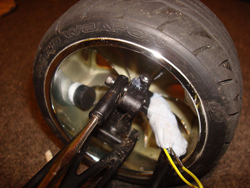
So there it is, a magnet mounted to the inside of the wheel, and a reed switch inside that big blob of blue tack. I connected the reed switch to the Arduino development board and also plugged in my SD card reader/writer that I made earlier. I was originally going to get the Arduino to do all the calculations and work out the speed to log to the memory card, but then I decided I would just log the milliseconds to the card each time the reed switch was activated.
My first test was just spinning the wheel by hand to see if it was all working, and this is the data I got back (after a bit of processing)
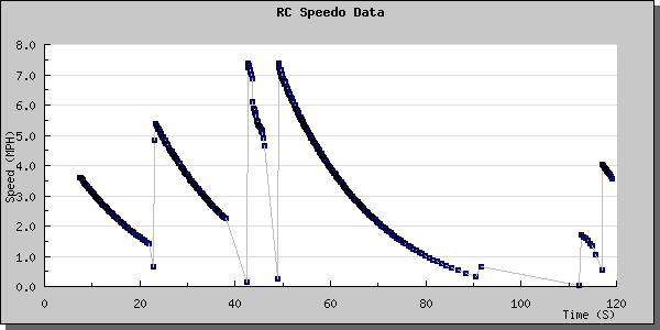
Beautiful :D
Probably not very well calibrated yet, I did measure the diameter of the wheel and do my best to get the calculations accurate, and this should be good enough for testing. Once I have a finished product I will calibrate more accurately.
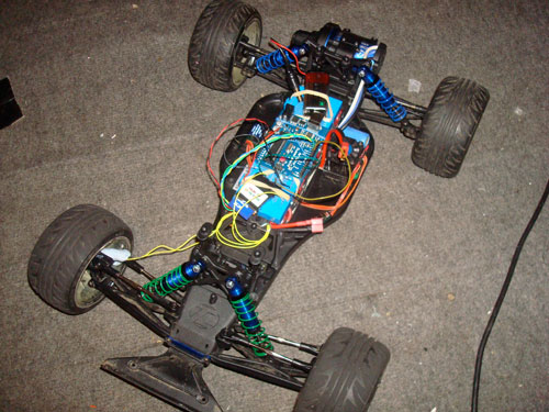
Right then, time to get the show on the road, literally. I managed to get the Arduino, SD card writer, and prototyping board with an indicaor LED and start stop button on to the car, as well as a 9v battery, which I soon removed as I wired the Arduino straight to the car's battery.
I drove around slowly in circles to begin with, everything seemed okay and nothing fell off so I thought I would knock it up a notch, I did flat out straight up the road, paused briefly and turned round, then did flat out straight back down the road. Then I went and did a few laps around a little triangle of trees at the end of the road. Here are the results...
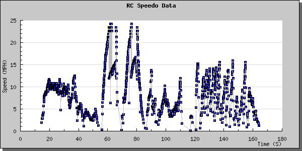
All looks promising at first glance, but wait a minute, we never seem to get above 25 MPH, in fact those two peaks in the graph between 55 and 85 seconds where I went flat out up and down the road should be up somewhere between 30 and 40 MPH. On closer inspection it looks like above 25 MPH the reed switch fails to register every revolution of the wheel. I thought to begin with that at higher speeds the magnet might go past the reed switch too fast to activate it, but if this was the case you wouldn't see any readings at all when I was above 25 MPH. It actually looks like the magnet has been passed to recently to be able to trigger the switch again, rather than is going past too fast to trigger it at all.
Perhaps some residual charge/field in the switch hasn't depleted and is stopping it activating every other revolution at high speeds. Perhaps a lower or higher pull up resistor would help, or maybe pulling down would be better. I am just clutching at straws here, can you tell?
What I have discovered now is something called a hall effect sensor, which measures magnetic field and will give an analogue output rather than a simple on or off that the reed switch does. Also there is no moving parts and I think it is much more sensitive and probably reacts a lot quicker. Unfortunately I can't source these from my local electronic shop and I'm having to place an order for them along with some other bits and bobs so it might take me a little while to get my order together.
I think this was quite a successful prototype and have great expectations for the hall effect sensors. I will be sure to post how that goes when I get them....
Version 2 - Hall Effect Sensor
The same principle applies as before, there is a magnet on the wheel that passes the sensor each revolution allowing the speed to be calculated. However the hall affect sensor is quite different from a reed switch. The reed switch is either on or off depending on whether it's been activated by a magnetic field. The hall effect sensor gives an analogue output measuring the strength and polarity of a magnetic field. This required a rewrite of the software, including a calibration function, and I also added some goodies while I was there.
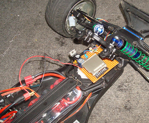
I used my strip board Arduino SD card writer for the main board for this project. I designed it with this project in mind so it already has three connectors to allow the hall effect sensor to be connected.
Calibration only needs to be done once, unless any of the hardware is changed or replace, and is performed by holding down the button whilst powering up the device. The magnet must be away from the sensor during this process. This takes a reading and stores the value to the ATmegas EEPROM. This is our baseline value, and as the wheel rotates and the magnet passes the sensor the current reading will stray from this baseline value, and we log the milliseconds taken since the last rotation to the memory card. There is a bit more maths and logic involved to try and reduce false readings, but I won't go into details here.
If the card is not present or failed to initialise the LED will flash constantly signifying a problem. Once the system is initialised the LED will flash once every time the magnet passes the sensor, and will also be logging this information to the card.
Before the card is removed the button must be held down until the LED is constantly lit, this flushes (writes) any data that has not yet been written to the card, much like un-mounting/ejecting your USB stick or memory cards before removing them from the computer.
The other goodies I mentioned is a race and driver selector. Pressing the button will mark the end of the current race and the beginning of the next race. The number of times the button is pressed in succession indicates which driver will be racing next. When reading the data into the computer this allows the data to be split into separate graphs for each race and they can also labelled with who was racing. An example follows of the results of me testing this functionality...
| Race # | Driver # | Race Time (Secs) | Top Speed (MPH) | Avg Speed (MPH) |
|---|---|---|---|---|
| 1 | 1 | 5.80 | 4.89 | 4.47 |
| 2 | 2 | 12.16 | 7.21 | 5.49 |
| 3 | 3 | 11.61 | 4.82 | 3.14 |
| 4 | 1 | 3.23 | 4.09 | 3.77 |
The graphs have been omitted, but this data table would be accompanied by four graphs, one for each race.
Time for a road test....
I mounted the device to the car, wired it up and power it on, and it initialised fine. I had a spin up and down the road and came back, pressed the button to start a new race with another driver number and had another spin, I did this several times with various different driver numbers and then flushed the buffer to the card. I took the card out and put it in my computer expecting to see quite a few different race graphs. I was only shown two races and graphs, one looked a complete mess and the other didn't really have much data on it at all. Here is the messy graph...
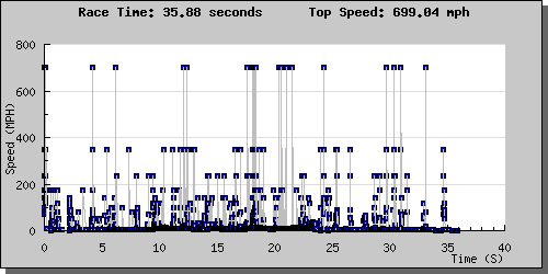
Not a lot of use, and I'm fairly sure it wasn't doing 700 mph. After a bit of an investigation I found the cause was electromagnetic interference from the car's motor or speed controller interfering with the readings from the sensor, also possibly interfering with the data being written to the card. I tried mounting the board in a grounded tin but that did not seem to help much. What seem to help most was moving the board away from the cars electronics and also twisting the hall effect sensors output signal wire with the ground wire. I also shortened the wires as much as possible.
Finally I got a sensible graph of me doing top speed, and here it is...
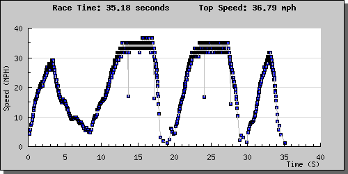
The points that look like they're in the wrong place, being much lower than the points around them are because a reading is missed every time a sector is written to the SD card. I'm sure this anomaly can probably be hidden in the software somehow, but are not overly concerned with this at the moment.
Still a fair bit of work to do, but a definite improvement on the first version which was unable to measure my top speed. Occasionally I seem to get no, or random data on the card and also my average speed calculation is far from accurate, but all things that I think have relatively easy solutions.
I guess I need to find some other drivers now and we can do some time trials and compare results :)