
I love my Arduino development board and have done some interesting experiments with it, and now I am at the stage of wanting to make some of my circuits a bit more independent and permanent, mainly so I can continue to use development board for tinkering with while leaving my other projects in a working state. The mind, body and soul of the Arduino is the ATmega168 chip, which contains all the memory, processor, analogue to digital converters and pretty much everything else. As these chips can be picked up for only a couple of pounds I thought I would have a go at making a stand alone unit to log data to an SD card...
I have made an SD card module for my Arduino before, so this is really about getting the ATmega chip powered up and running and interfacing to the module, for more information about the SD card project and the software involved see my SD card and Arduino post.
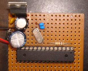
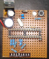
At this stage it is pretty generic, all that it consists of is a power supply (5 V regulator, protective diode and resettable fuse, and a couple of smoothing capacitors), a 16 MHz crystal with two capacitors, and the ATmega168 chip whith a 10 KΩ pull up resistor on the reset pin, I chose not to have a reset button but this could easily be added. This seems quite a nice layout and could be a good starting point for many different projects. Most of the chips Digital I/O pins are accessible, and so are all of the analogue input pins.
One thing the development board does give you is a USB port, allowing easy programming of the chip. To programme this chip I simply pop the chip out of its socket and place it back in the development board, upload the programme and then pop the chip back into my board.
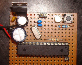
Here I have added a pushbutton and LED with 330 Ω resistor to digital I/O pin zero and one respectively. You pretty much always need some sort of input and output, these were very useful during debugging, and essential for communication between the running programme and the user. The pushbutton does not need a pull up resistor as the ATmega168 has internal pull up resistors that can and will be enabled in my code. I have also added three connectors to allow external access to ground and 5 V, and also analogue input zero.
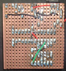
This next stage shows the connector to mount my SD card socket onto. It is actually half a chip socket that I have cut up, bent the pins slightly and tinned. There are also three voltage dividers used to drop the 5 V output logic from the ATmega down to the 3.3 V required for the SD card.
I ran into a bit of a problem at this point, in my haste to build this circuit and as I had also made an SD card module for my Arduino before I didn't test this part when building the prototype. This was a big mistake! What I had done was used the same voltage divider method to drop the 5 V supply voltage down to 3.3 V to supply the SD card, however it turns out that this is not a good thing to do, it is fine for the logic but not the supply. The voltage isn't particularly stable, as when the internal resistance of the card changes it upsets the ratio of the resistance in the divider.
After muttering some obscenities and returning to the prototyping board I found a 22 µF or greater capacitor across ground and 3.3 V helped slightly, allowing the MMC library to initialise, but failing at the second hurdle now with the microfat library failing to initialise. I somehow needed a very stable 3.3 V supply. I didn't really really want another voltage regulator on my circuit, then I remembered our good old friend the zener diode! Using a 3.3 V reverse biased zener as the lower side of the voltage divider and a smaller resistor above (47 Ω) I was able to achieve a steady voltage, and the card initialised perfectly.
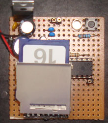
So here it is now with the card holder and card attached, all working and tested. It is probably a bit hard to follow the wiring from the photographs, so I have also included schematic. This is a nice compact but minimal package, with a lot of the input pins available for reading data and a card to log that data to. I can imagine many uses for this, and there is even a little bit of space on the board for a fewer additional components should they be required.
- Log in to post comments